V2 rocket injector head – LOX Spray nozzle 1
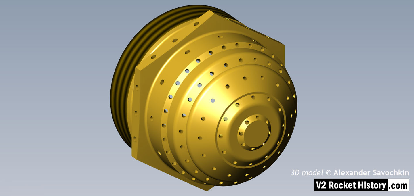
Brass liquid oxygen (LOX) spray nozzle.Note: the thread is shown in simplified graphic form. 3D model by Alexander Savochkin
Album: Anatomy of the V2: 18-pot injector head
Categories: Anatomy of the V2 Combustion
Tags: